Casual Tips About How To Build A Logic Probe

0:00 / 18:55.
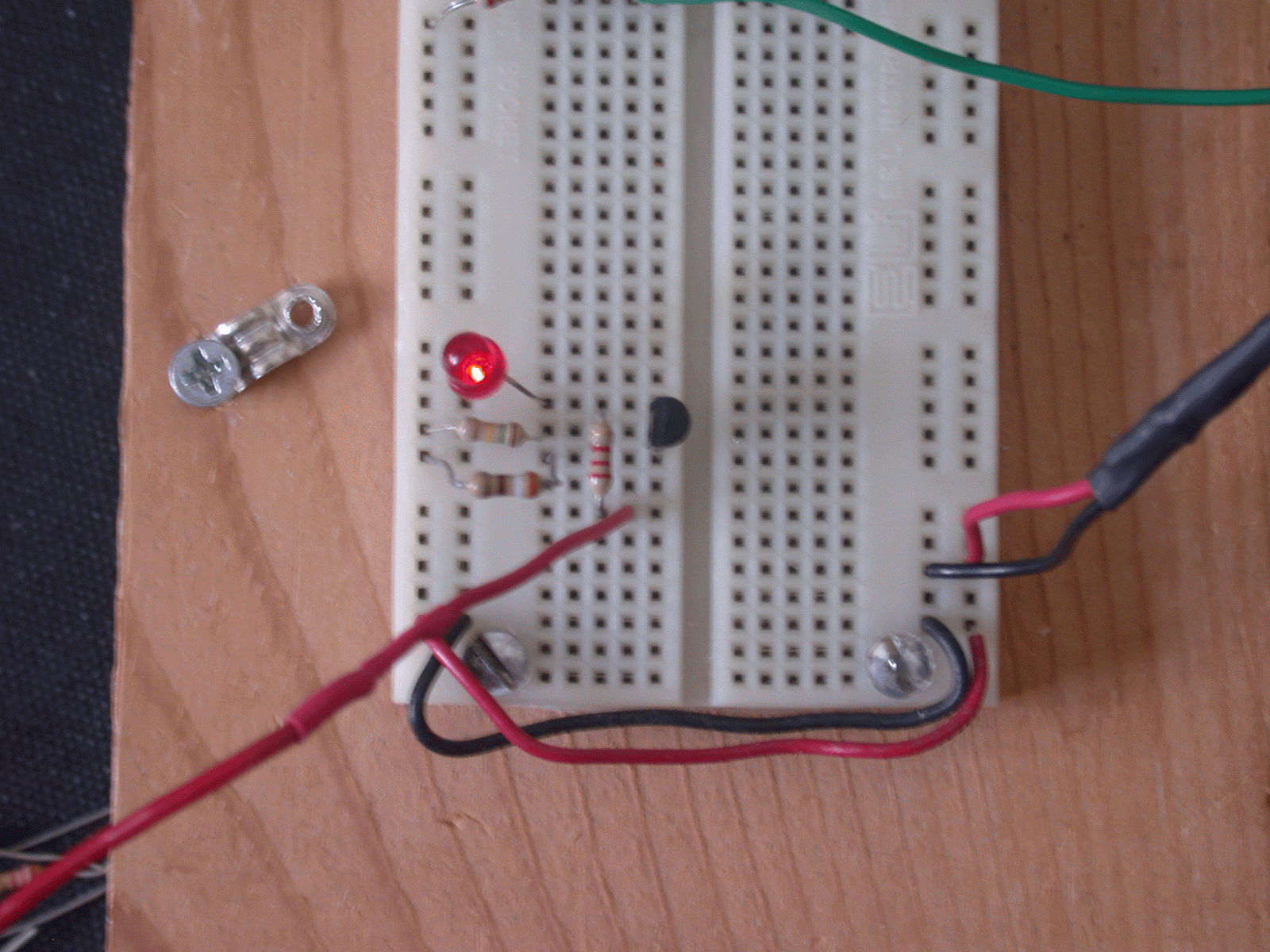
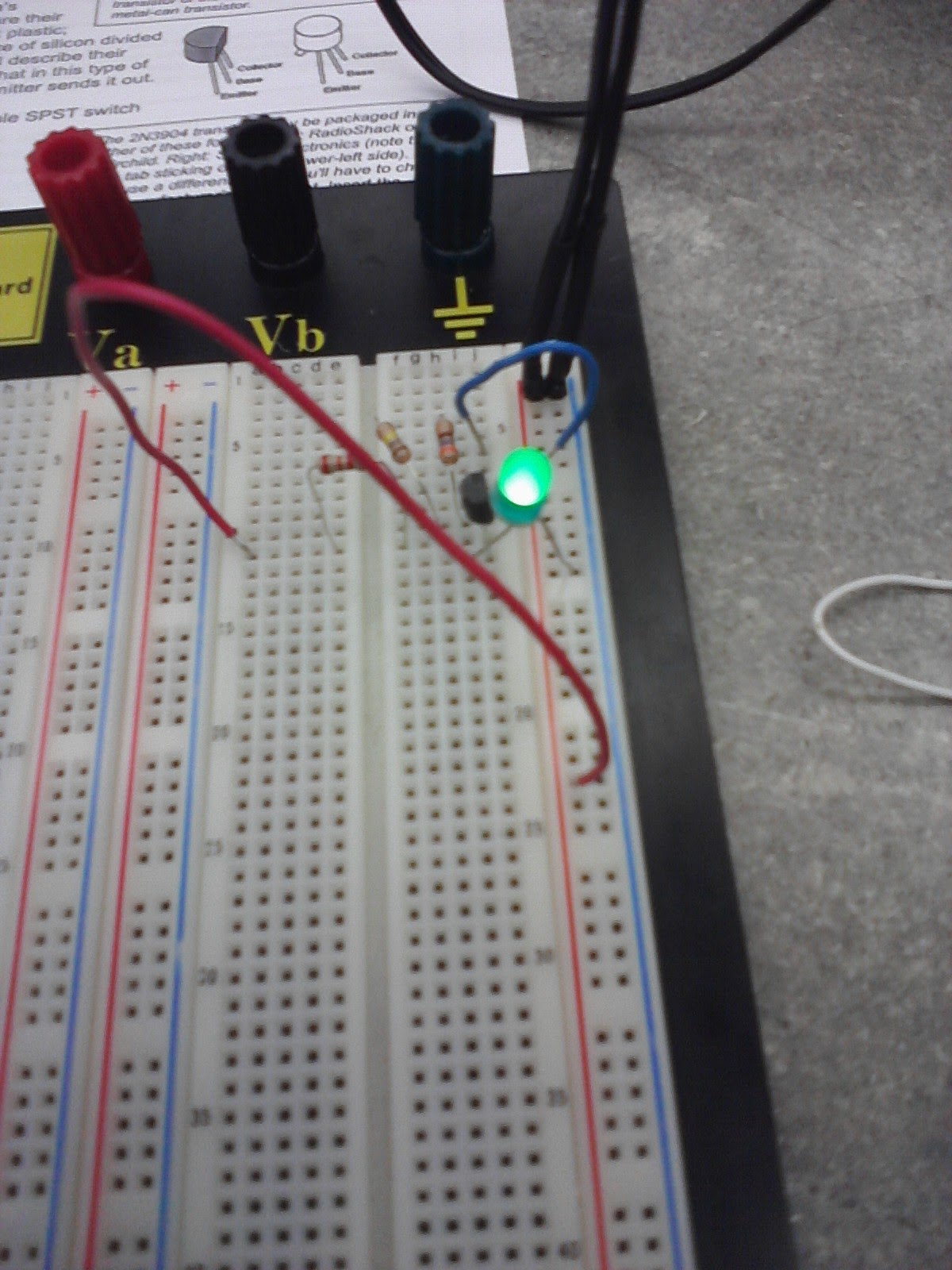
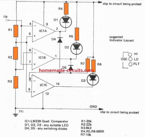
How to build a logic probe. It is a very simple construction unlike the dual comparator circuit in the second picture. How to make a logic probe #1960. Build a logic probe ttl / cmos.
How to build logic probe. By bianchi gabriele on july 30, 2021. 28k views 6 years ago.
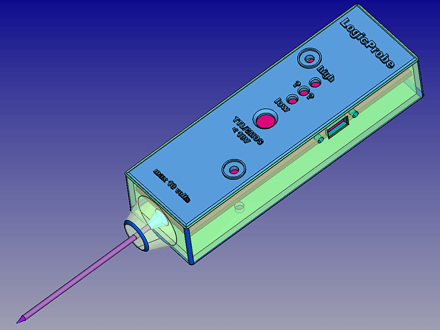
A logic probe with an led binary visual indicator display. in this project, we will build a programmable logic probe. With the advancement of oscilloscopes, simple testing tools such as logic probes are not as popular these days. When many signals need to be.
This circuit is a logic probe. The value of the resistors r must only be equal but, it is. This simple gadget shows you the logic.
In this project we see how to build a logic probe, that is a complete, simple and effective. A logic probe with h or l visual indicator display. figure 3. In this video, james makes a counter circuit and debugs each stage as he builds, with a logic probe.
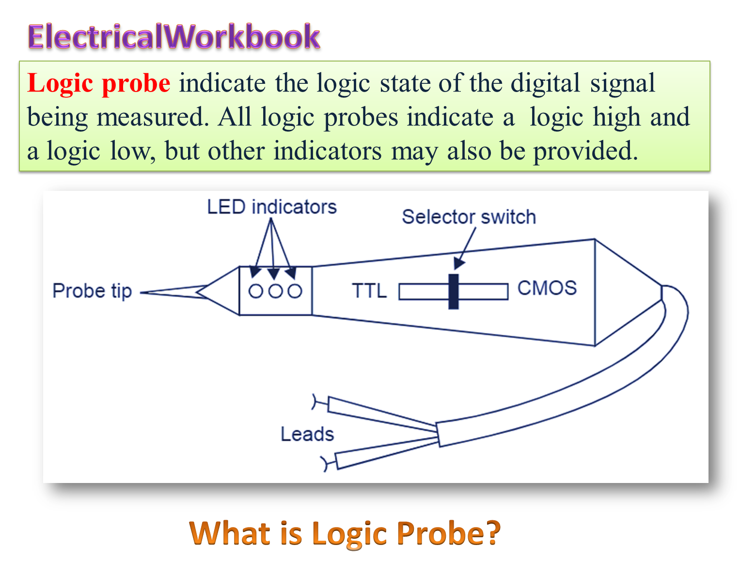
This circuit is a logic probe. Logic probes are great for debugging 7400 series logic chips and digital circuits. It indicates the logic state of the node of any ttl logic circuit.
2.3k views 4 years ago. Making your own universal logic probe. One of the many workshop tasks that i cover.
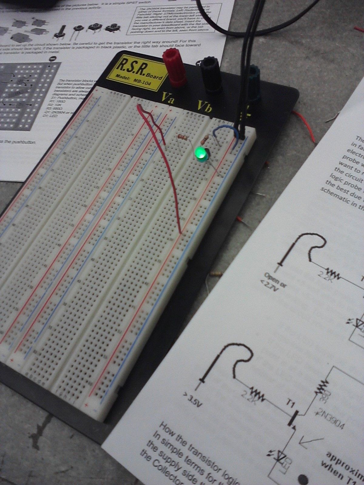
Logic probe circuit schematic diagram. 1) simple logic probe using transistors. A quick introduction to using a logic probe in digital circuits.
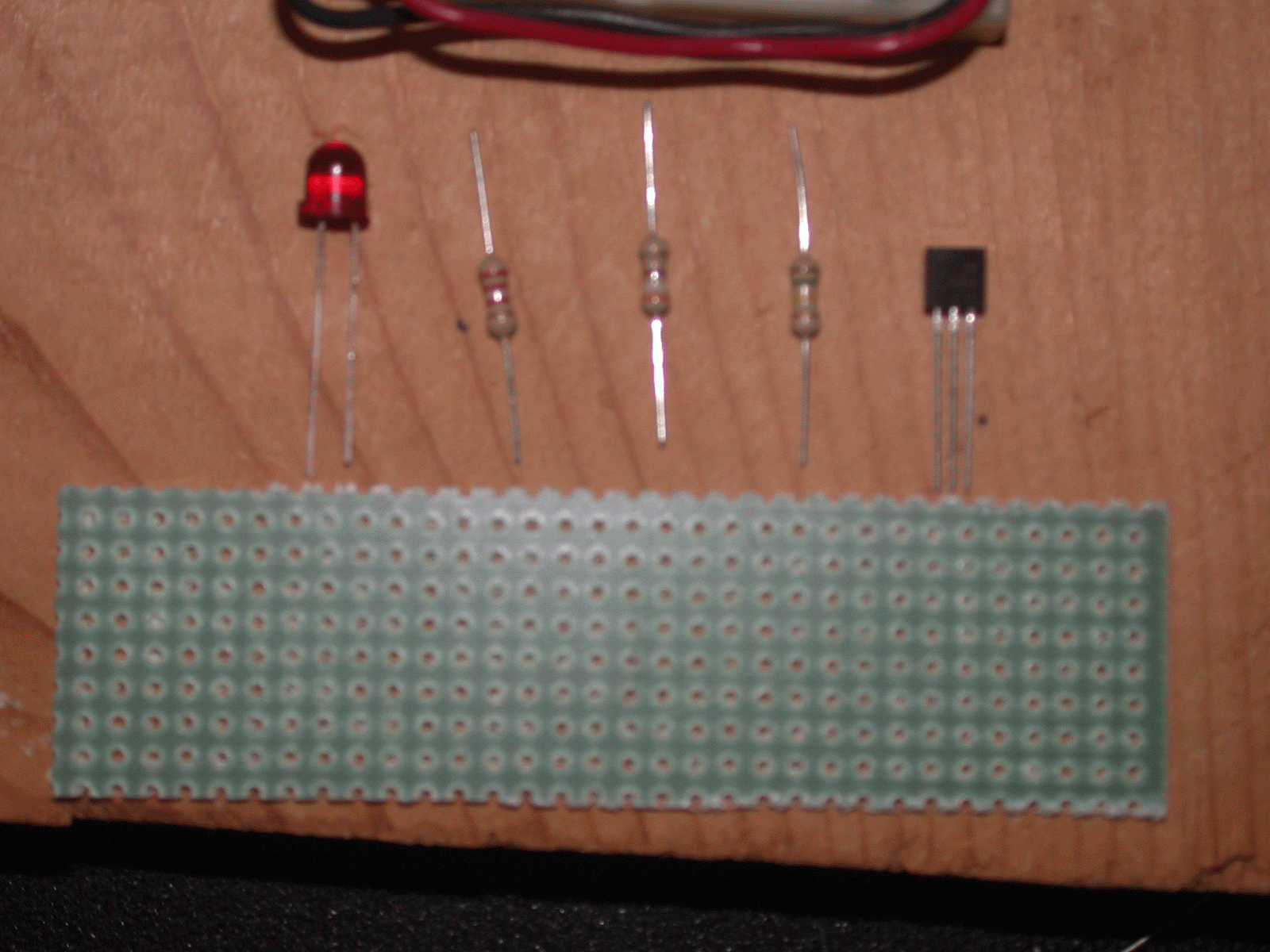
To do that, we have to. Here's the components needed to build the logic probe shown in the bill of materials (bom) picture. This first design is a very simple logic probe circuit which is build using only transistors and bjts.
A functional logic probe is one of the handiest tools you can have in your electronics workbench. Not only can sigrok decode raw voltages into. Logic probe kit instructions.
